
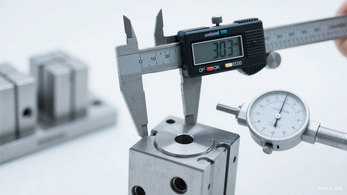
Tolerance specification is one of the most critical aspects of mechanical part design. The tolerances you specify directly impact manufacturing costs, production methods, and part functionality. Understanding how to select appropriate tolerances helps optimize both performance and economics in precision machining projects.
What Are Tolerances?
Tolerances define the acceptable deviation from nominal dimensions. No manufacturing process can produce parts with perfect dimensional accuracy—variations inevitably occur due to machine capabilities, tool wear, material behavior, and environmental factors. Tolerances establish the range of variation that still allows parts to function correctly.
A tolerance might be expressed as a bilateral value (such as +/- 0.05mm) indicating acceptable deviation in both directions from nominal, or as unilateral values specifying different limits for oversize and undersize conditions. Geometric tolerances control form, orientation, and position relationships between features.
Standard vs. Precision Tolerances
Standard tolerances represent what modern CNC machines can achieve without special processes or extraordinary care. For typical CNC milling and turning operations, standard tolerances range from +/- 0.05mm to +/- 0.1mm for linear dimensions. These tolerances are achievable with normal machining practices and represent economical production.
Precision tolerances require tighter control, typically ranging from +/- 0.01mm to +/- 0.025mm. Achieving these tolerances demands higher-quality machines, more careful process control, additional inspection, and often slower production rates. Precision tolerances significantly increase manufacturing costs compared to standard tolerances.
Typical Tolerance Ranges:
- Standard CNC: +/- 0.05mm to +/- 0.1mm (economical)
- Precision CNC: +/- 0.01mm to +/- 0.025mm (moderate cost increase)
- High Precision: +/- 0.005mm or tighter (significant cost increase)
- Ultra Precision: +/- 0.001mm (specialized processes, highest cost)
Cost Implications of Tight Tolerances
The relationship between tolerance tightness and manufacturing cost is exponential rather than linear. As tolerances become tighter, costs increase dramatically because achieving precision requires:
- More expensive, higher-precision machine equipment
- Slower cutting speeds to minimize vibration and deflection
- More frequent tool changes to maintain cutting accuracy
- Additional inspection steps and measurement equipment
- Higher scrap rates when parts fall outside tolerance
- More skilled operators and process engineers
"Specifying tighter tolerances than functionally necessary is one of the most common causes of excessive manufacturing costs. Every unnecessary precision requirement adds cost without adding value."
Industry studies suggest that reducing tolerance requirements from +/- 0.025mm to +/- 0.05mm can reduce machining costs by 40-60%. Further relaxation to +/- 0.1mm may reduce costs by an additional 30-40%. These savings compound across production volumes, making tolerance optimization highly valuable.
When to Use Precision Tolerances
Precision tolerances should be specified only when functionally necessary. Critical applications requiring precision tolerances include:
- Mating surfaces where precise fit controls clearance or interference
- Bearing seats and shaft fits where dimensional accuracy affects performance
- Sealing surfaces where leakage prevention requires precise geometry
- Alignment features where positioning accuracy is critical
- High-speed rotating components where balance and concentricity matter
For non-critical features—cosmetic surfaces, non-mating dimensions, structural elements with generous clearance—standard tolerances are entirely appropriate. Applying precision tolerances universally across all features unnecessarily inflates costs without improving product performance.
Geometric Tolerances Beyond Linear Dimensions
Geometric dimensioning and tolerancing (GD&T) provides sophisticated control of feature relationships beyond simple linear dimensions. GD&T symbols specify requirements for flatness, perpendicularity, concentricity, position, and other geometric characteristics that linear tolerances cannot adequately control.
Proper GD&T application often allows looser individual tolerances while ensuring functional assembly through geometric controls. This approach can reduce costs compared to applying tight linear tolerances everywhere. Understanding GD&T principles enables more effective tolerance specification.
Best Practices for Tolerance Specification
Effective tolerance specification follows several key principles:
- Apply tight tolerances only to functionally critical features
- Use standard tolerances for non-critical dimensions
- Consider GD&T for complex geometric requirements
- Account for assembly stack-up when specifying tolerances
- Discuss tolerance requirements with manufacturing engineers
- Document the functional rationale for tight tolerance requirements
Collaborating with manufacturing partners during design development helps identify where tolerances can be relaxed without compromising functionality. This collaborative approach produces designs optimized for both performance and cost-effectiveness.