
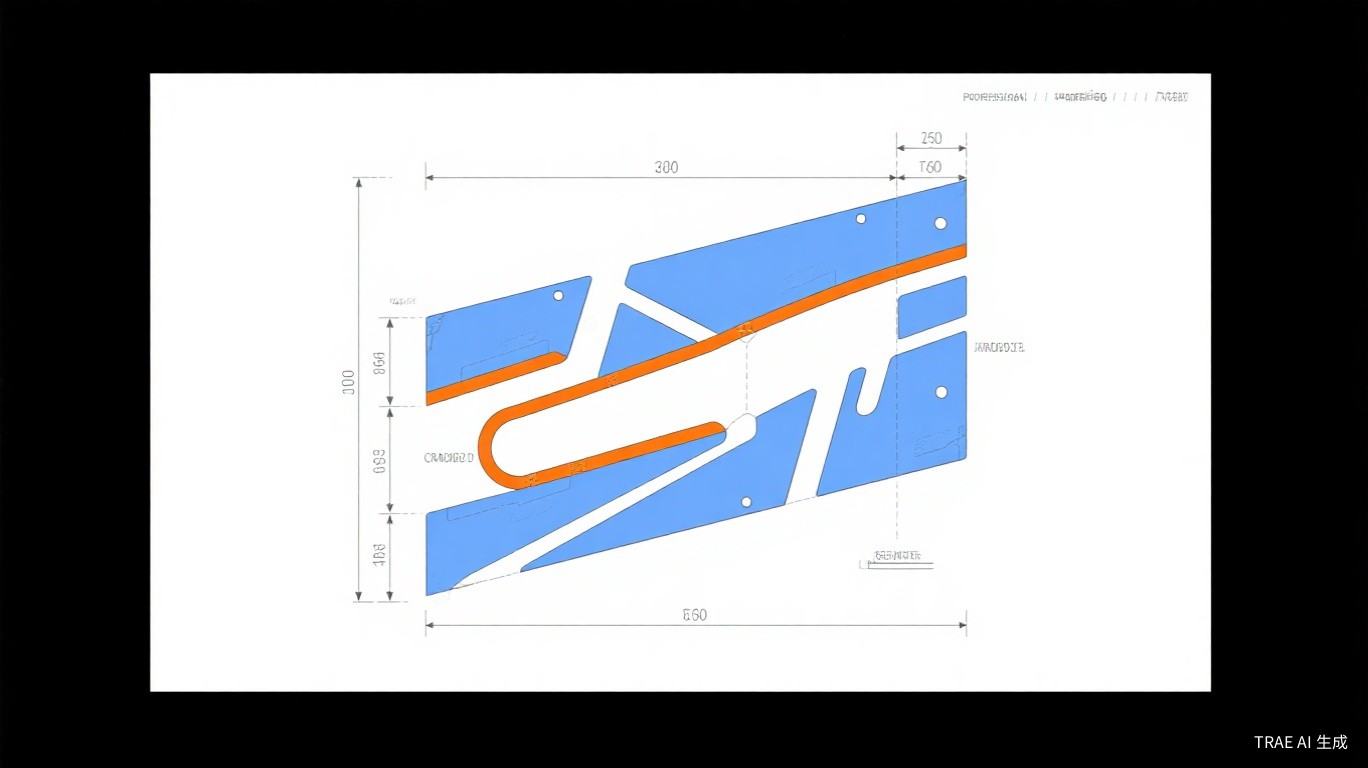
Effective sheet metal design is critical for achieving cost-effective production, consistent quality, and optimal part performance. Understanding fundamental design principles helps engineers create parts that can be manufactured efficiently while meeting all functional requirements. This guide covers essential considerations for successful sheet metal design.
Understanding Bend Allowances
When sheet metal is bent, the material on the outside of the bend stretches while the material on the inside compresses. This deformation creates a neutral axis where the material neither stretches nor compresses. The bend allowance accounts for this material behavior and is essential for calculating accurate flat pattern dimensions.
The bend allowance depends on several factors including material type, thickness, bend radius, and bend angle. Different materials exhibit different elongation characteristics, and thicker materials require larger bend allowances. Standard formulas and industry tables provide bend allowance values for common materials and configurations.
Bend Allowance Guidelines:
- Minimum bend radius should equal material thickness for most applications
- Harder materials require larger bend radii to prevent cracking
- Bend allowance increases with material thickness
- Use established K-factor values for accurate calculations
- Consider springback when designing critical dimensions
Hole Placement Near Bends
Placing holes too close to bend lines causes distortion during forming operations. The bending process stretches material in the bend zone, and holes within this zone will deform from their original circular shape. Maintaining adequate distance from bend lines preserves hole integrity and ensures proper fastener fit.
The recommended minimum distance from hole edges to bend lines is 1.5 to 2 times the material thickness. For holes requiring precise dimensions or tight tolerances, even greater distances are advisable. When design constraints require holes closer to bends, consider secondary operations after forming or alternative design approaches.
"Proper hole placement is one of the most overlooked aspects of sheet metal design. Holes placed too close to bends not only distort but can also weaken the structural integrity of the flange."
Flange Design Considerations
Flanges provide structural reinforcement, mounting surfaces, and assembly interfaces in sheet metal parts. Effective flange design balances functional requirements with manufacturability. Minimum flange heights depend on material thickness and the forming tool capabilities available.
For standard press brake operations, minimum flange height should be at least 4 times the material thickness plus the bend radius. Shorter flanges may be possible with specialized tooling but typically increase production costs. Flange width should be sufficient to support intended loads while allowing adequate tool access during forming.
Flange Design Best Practices:
- Minimum flange height: 4T + bend radius (T = thickness)
- Avoid flanges shorter than tooling minimums
- Consider flange orientation for assembly accessibility
- Design relief notches at flange corners to prevent tearing
- Account for material springback in flange angle design
Material Selection for Sheet Metal
Material selection significantly impacts both manufacturability and part performance. Common sheet metal materials include various steel grades, aluminum alloys, stainless steels, and specialty materials. Each material type offers distinct characteristics affecting forming behavior, corrosion resistance, strength, and cost.
Mild steel offers excellent formability at low cost, making it suitable for general applications. Aluminum alloys provide lightweight solutions with good corrosion resistance but require careful design consideration due to different forming characteristics. Stainless steels offer superior corrosion resistance but are more challenging to form and more expensive.
Common Sheet Metal Materials:
- Mild Steel (CR/HR): Excellent formability, economical, versatile
- Aluminum (5052, 6061): Lightweight, corrosion resistant, good formability
- Stainless Steel (304, 316): Superior corrosion resistance, higher strength
- Galvanized Steel: Corrosion protection, economical for outdoor use
- Brass/Copper: Decorative applications, electrical conductivity
Corner Relief and Notch Design
When flanges meet at corners, the intersecting bend lines create material conflicts that can cause tearing or distortion. Corner relief notches remove material from these intersection zones, allowing clean forming without material interference. Proper relief design prevents quality issues while maintaining structural integrity.
Relief notches should extend beyond the bend zones and have rounded corners to prevent stress concentration. The notch width should be slightly larger than the material thickness to ensure adequate clearance. For enclosed corners, relief holes or mitered corners provide alternative solutions.
Design for Cost-Effective Production
Beyond technical requirements, effective sheet metal design considers production economics. Simple designs with standard bend radii, adequate flange heights, and generous hole-to-bend distances minimize tooling requirements and setup time. Reducing the number of distinct bend operations and avoiding complex geometries decreases production costs.
Standardizing material thicknesses across product families enables efficient nesting and reduces material inventory. Designing parts to fit standard sheet sizes minimizes waste. Considering orientation for efficient nesting during laser cutting or punching operations further optimizes material utilization.
Working closely with manufacturing engineers during design development identifies potential issues early when changes are least costly. This collaborative approach produces designs that meet functional requirements while maximizing production efficiency and minimizing costs.